|
|
||||||||||||||
|
More Than Just Speed Mods Part Deux by Hans Neubert
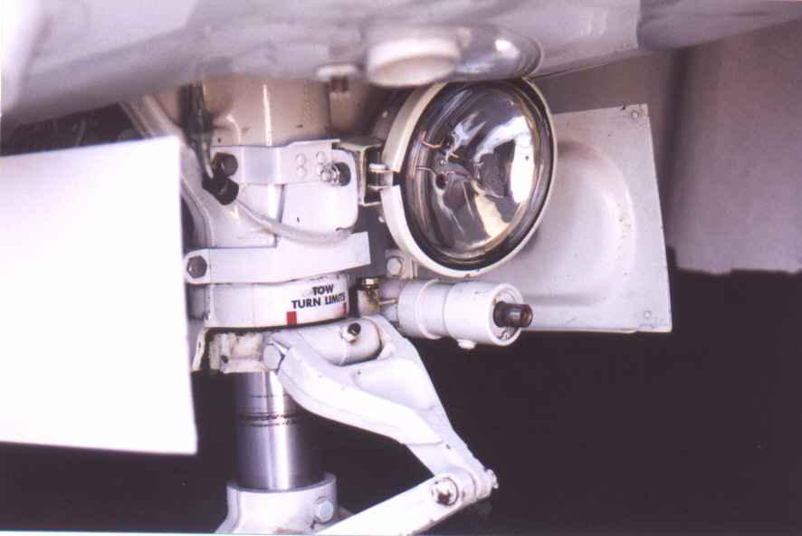
"It was a dark and stormy night!" Well, actually, it was a dark and clear night. Earlier in the day, I had taken an acquaintance and two of his assistants from Chino to Visalia, California to bid on some earth moving equipment, with a stop-over at Tehachapi to look over property they were developing. After dinner there, it was back to airport for the return flight. This small town airport is located in the hills northwest of Mojave at 4,000 feet elevation, with a 4,000 foot runway. Night lighting at the airport is minimal. After everyone was situated, we started out on the ramp, looking for the taxiway. Everyone knows that the two landing lights at the wing tips are focused at about 500 feet ahead of the plane, leaving a dark, triangular 'black hole' in front of the plane. As I taxied out, I missed the turn for the taxiway, and almost went off the ramp into a deep ditch. Did I mention that it was really dark outside? Taxi Lights Not wanting to repeat that episode again there or anywhere else, I developed a taxi lighting system for the plane. The nose light consists of a Whelen A715-1 fixed landing light, as used on Cessna and Beech twins. The supporting bracket is made from mild steel and aluminum. The location of the light and the mounting hole were determined by trial and error, meaning I had to make the parts a few times to get the location just right. It is a tight fit.
At present, the nose light is not steerable. But when time permits, that feature will be added.
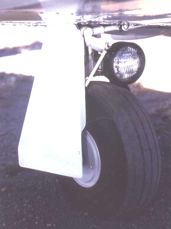
The light on each main landing gear leg is an off-road truck light incorporating a PAR 36 bulb. The housing is neoprene rubber, well suited to absorb any shock loads during landing. Each bracket is constructed of aluminum plate with a steel support for the light. The bracket uses the two unused holes on the back side of the gear trunnion and the forward bolt between the trunnion and the oleo tube. It also took a few tries to get these lights to fit properly, and aim them for maximum night lighting effectiveness. The photo of the main landing gear light shows the 35W flood light bulb that came with the unit, but I have since changed out to Halogen H7604 bulbs everywhere. So now, when I land anywhere at night, I can see where I'm going. I realize that some pilots like to use a hand portable 1 million candlepower light, which is a lot simpler, but there is some gratification when people on the ground see me on approach and think a B-707 is going to land at their airport. Switches Two heavy duty double pole, single throw switches were purchased to replace the existing SPST landing light switches. On one switch, both landing lights were connected to the new switch using existing wiring. On the other switch, connections are ganged together to operate the three taxi lights. New wires, circuit breaker, and connectors were used in installing the taxi lights, with both new switches being situated in the existing holes.
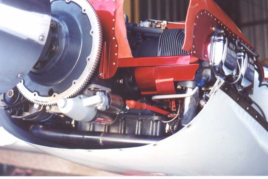
Cowl Internal Airflow Baffle As I have previously mentioned, there is a need for sealing the cowl to minimize air leaks. While on a cross country flight, I noticed I was getting significant oil leakage from my newly overhauled engines. I was not a happy camper. Back in the hangar, I also observed lots of oil on my recently overhauled props, and elsewhere. Not good. To cut to the chase, it turns out that both crankshaft nose seals had blown out, and were dangling on the crankshaft. A reason for this occurrence, even to this day, has not been established. New crankshaft seals were installed under warranty, but the prop shop indicated that nothing was wrong with the prop seals. Air enters the engine cowl through the two inlet holes, passes over the cylinder fins, and exits through the opening at the bottom of the firewall controlled by the cowl flaps. But wait; air can also escape by flowing forward and passing through the nose bowl and spinner and out along the blades. Since this airflow is opposite the direction of flight, another modification was in order. Using some thin acrylic sheet, templates were made with scissors, cut and paste fashion. After a few tries, a final configuration was established, which was carefully measured and drawn up in CadKey, a computer drafting program. Once in a digital format, the drawing was imported into MasterCam, a CNC programming software, and finally into CNC machine instructions. Before and after views of the engine cowl are shown below. An added benefit is that I am learning a new skill: CNC programmer and machine operator. Lower Cowl before adding baffle
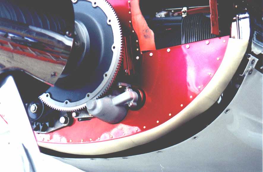
Below - Lower Cowl with added baffle and seal
The baffle is fabricated from .032 aluminum, while the seal is fabricated from silicone sheet material, then cured at 350°F before being riveted to the baffle. The baffle is in two parts, with one part sealing above and inboard of the alternator, and the other, a full width piece. Since this modification, I have not observed any oil streaks anywhere along the nose bowl hinges. Now, when I close the cowl flaps in cruise, there is high confidence that all air entering the cowl will indeed exit out the prescribed location at the bottom of the firewall. External Power Plug Relocation On my particular '64 twin, the external power plug is just aft of the baggage door. As part of the new paint job, I had the shop make up some brackets and relocate the power plug above and outboard of the battery. A hole was cut in the rear panel of the baggage compartment and a hinged door installed, allowing easy access to the power plug should the need arise. Meanwhile, the original external hole is patched flush, leaving the airplane with a clean look. Epilogue While it is now time to finish up these two articles, it is not the end. I still have some more ideas in the works, and I'm currently working with Horizon Instruments to install some of their new digital engine gauges. The airplane is really nice to fly, and I have had many hours of pleasure in it.
Hans and Jeannie Neubert Hans has BSME and MSAE degrees, with 35 years of experience in the aerospace industry. He is expert in materials, design and analysis of composite materials in aircraft and spacecraft structures. Hans is also an FAA Designated Engineering Representative (DER) in structures, with approval authority on Part 23 and Part 25 aircraft for major/minor structures and repairs, including non-metallic (composite) structures. |
|||||||
|
|
|||||||